
 DFM: CONCURRENT COSTING
 DFA: PRODUCT SIMPLIFICATION


Design for Opportunity with DFA
Design analysis software helps instrument builder develop a new product in time to capture a healthy share of the market
Whenever a window of opportunity opens for introducing a new scientific instrument, MDS SCIEX (Concord, Ontario) leaps through it confidently. Such was the case a few years ago when the opportunity arose to develop a hybrid mass spectrometer combining time-of-flight technology with conventional quadrupole designs. The new design had been gaining favor among chemists because it widened the range of compounds that laboratories could analyze and identify – from naming simple compounds to distinguishing differences among molecules as large and complex as DNA.
Management at MDS SCIEX, a division of MDS Inc. and a leading manufacturer of quadrupole mass spectrometers, knew it had to act fast to capture a healthy share of this new hybrid market before the window closed. The company had only 12 to 15 months to bring to market a commercial product that chemists could use out of the box. In early 1998, management set into motion the QSTAR project, the largest product development program in the company’s 25-year history. The 75-member development team transformed a breadboard developed by scientists in the research laboratory into a high-quality, cost-competitive, shippable product that did not require onsite assembly and a technician to install.
Achieving these goals was an enormous challenge because breadboards are essentially science experiments for proving concepts and are much too complex to build and use. “Each one is custom assembled and tweaked,” says George Valaitis, manager, mechanical engineering. “The scientists file parts to fit and wire pieces together.” Consequently, teams of design and manufacturing engineers must work with the scientists to convert breadboards into commercial products. Even after simplification, the QSTAR contained 8,000 parts, 1,500 of which are uniquCoordinating the large number of people involved in bringing this complex instrument to market required a highly disciplined approach. The engineering team used Design for Assembly (DFA) software, part of the Design for Manufacture and Assembly (DFMA®) series of software from Boothroyd Dewhurst, Inc. (Wakefield, R.I.). In addition, the team relied upon the Six Thinking Hats® brainstorming technique developed by Dr. Edward de Bono. “The DFA software was a catalyst to stimulate discussion and to guide technical analysis of the design,” says Valaitis. “The Six Hats method kept our discussions focused so the design work would stay on schedule.”
Beyond the Breadboard
QSTAR mass spectrometers are large, sophisticated instruments produced in low volumes. The manufacturing team recognized that ease of assembly would largely determine the cost, manufacturing efficiency, and field performance for the product. As originally constructed, the breadboard was difficult to assemble and needed days of testing and tweaking to find its sweet spot for performance.
Redesigning the QSTAR so it had as few components as practical, and devising components that were self-jigging and self-locating, were important goals for simplifying the breadboard. The QSTAR engineers used DFA software to analyze the existing design and to spark innovative ways to consolidate parts and eliminate assembly difficulties. After the DFA software guided the design teams through a round of improvements, the version of QSTAR that went into production achieved tight mechanical tolerances without requiring post-assembly adjustments.
Another goal was to stabilize the instrument and its modules for shipping. Because the scientists who developed the breadboard exploited gravity to hold some components together, the device could not withstand any side loads. Moreover, some of the major subassemblies in the breadboard were fragile. Precision components were stacked on top of each other like building blocks. To add support and improve the tolerances, the new design called for hanging components and modules from a supporting structure, rather than stacking them. Tests of the redesigned instrument showed it could withstand side loads as great as 8 g.
One of the most important assemblies designed with the aid of DFA software was the flight tube, an added component that allows the traditional quadrupole apparatus to generate orders of magnitude more data about the substance being tested. After an ionization process strips an electron from each molecule and the newly charged particles enter a vacuum chamber, two sets of precisely machined and coated dipoles sets the particles into motion, sending them through a series of filters and into a uniform stream. A particle accelerator shoots the stream of ions down the flight tube toward a series of coils that reflects them back to an ion detector. Because heavier particles take longer to bounce back, the device can systematically calculate the atomic mass of particles and identify the substance.
“We answered the questions in the DFA software one by one,” says mechanical engineer Goran Marunic, a member of the flight tube development team. “The questions prompted a series of discussions about part count and assembly efficiency. Working closely with manufacturing engineering, we kept the design modular, aiming for more manageable development and better assembly and serviceability. We divided the design logically into subassemblies, each of which had its own bill of materials.”
Carrying good design-for-assembly practices even further, Marunic and his team also designed the subassemblies of the flight tube to be self-fixturing and self-centering modules. The ion detector and accelerator assemblies fit only one way, so assembly mechanics can insert them correctly every time and not have to spend time adjusting alignments.
Focus on the Reflector
The reflector subassembly was a critical module in the flight tube and the most fragile component in the breadboard. Consequently, the reflector subassembly was subjected to several analyses with the DFA software. “We debated its design right up until we finished conceptualizing the product,” recalls Marunic. “Marketing did not want to have to ship it separately and assemble it in the field. Initially, we analyzed the breadboard instrument with the DFA software. After thinking about the results and improving the reflector module, we used the software again to validate our concepts.”
One problem the software flagged was the insulation separating a series of metal rings that line the reflector section of the flight tube. In the breadboard, ceramic balls were used as spacers between each metal ring to regulate the -5 to +1 kV potential across the assembly. “Although the balls insulated the parts and made the rings self-centering, they were not shippable,” says Marunic. “They crumbled when subjected to vibration or a load from impact. So during design, we moved from ceramic balls to flat ceramic spacers to sheets of Kapton.” The Kapton sheets cut cost tremendously and led to a rugged assembly.
The DFA software also flagged the number of fasteners connecting the stack of resistors and metal rings. In the initial concept, the scientists had mounted each of the 32 resistors in the breadboard with four screws, which contributed heavily toward the 8-hour assembly time. “As an alternative, we designed a connection that allows a technician to press the resistors into the metal part,” says Marunic. “Because they require no screwing, they’re quick to assemble and easy to replace.”
In the end, the QSTAR team designed a reflector subassembly that can be put together in only 45 minutes and can be removed and serviced without disrupting the rest of the instrument. Whereas the breadboard reflector contained 289 parts with 26 unique components, the final reflector module contains 144 parts with 21 unique components. Only three screws and three nuts hold all 144 parts together. Better parallelism was another important result. “Parallelism was a parameter we had to control closely to meet the marketing department’s performance requirements,” reports Marunic. “If the flight tube were not parallel, then one side of the relatively wide particle beam traveling through it would reach the detector before the other.” Parallelism in the first two assembled prototypes of the reflector was measured at 0.00043 inches and 0.00063 inches, more than an order of magnitude tighter than the 0.002 inches achieved in the breadboard and the goal of 0.00125 inches set for the final commercial version. What makes this feat of accuracy even more phenomenal is the fact that tolerances were measured over a stack of 144 parts.Quality Control Plan Pays Off
Quality Control Plan Pays Off
From the beginning, the QSTAR engineers followed design practices that helped them avoid quality control and troubleshooting problems in manufacturing. Key elements of their strategy were to design the instrument in modules and to identify measurable parameters that would indicate the instrument’s ability to perform in the field.
Parallelism of the flight tube assembly is one such parameter. Because the offset voltage across the flight tube is a function of how parallel the tube is, the QSTAR development team decided that measuring the voltage would be a quick quality control check of parallelism. They specified a tolerance of –31 V to +7 V for the offset voltage. After assembly, the instrument goes to a final testing station, and an inspector measures the offset voltage and other parameters and plots them on a control chart.
If offset voltages or other values wander out of tolerance, a team of investigators can exploit the modular design of the QSTAR to find the source of the problem. “By designing the critical components and subassemblies as modules, we can replace them to see which module influenced the performance of the machine,” explains Marunic. Meanwhile, the ability to swap subassemblies allows production to rework only the module in question, rather than tying up an entire assembly bay while technicians isolate and correct the problem.
In August 2000, after production of an improved generation of the product was well underway, a problem surfaced that put this scheme to the test. Several offset voltage measurements were suddenly at or near the lower tolerance limit. Although the instrument passed inspection, the trend indicated a problem somewhere in the manufacturing process. “Because of the modular design, we were able to isolate the subassemblies that were degrading the performance of the machine and trace the problem to a particular vendor,” says Marunic. In the midst of changing ownership, one machine shop had stopped checking some part dimensions specified in the original certification.
“We were able to find the problem and correct it quite quickly without disrupting production,” notes Marunic. Considering that QSTAR mass spectrometers sell for $300,000 to $450,000 each, designing in the flexibility to troubleshoot and correct problems without halting production saved a lot of money.
Design for assembly practices saved money in other ways, too. By reducing the part count, QSTAR engineers cut materials costs by $35,000 per unit and reduced opportunities for design and manufacturing errors. Marunic estimates that engineering corrections made per part for the QSTAR amounted to less than half those made for three of the company’s earlier mass spectrometers.
Most importantly, DFA helped shorten the development cycle by 20 percent. MDS SCIEX management calculates that getting to market in 14 months increased revenue by $20 million and allowed the QSTAR to capture one-fifth of the global market in the first year of sales. For a company that plans to continue leaping through windows of opportunity, that’s a welcome landing.
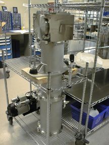
View of the flight tube of the QSTAR triple quadrupole mass spectrometer. MDS SCIEX used Design for Assembly software from Boothroyd Dewhurst, Inc., to optimize the design of modular components for the flight tube, including the ion detector, the accelerator, and the reflector subassembly.
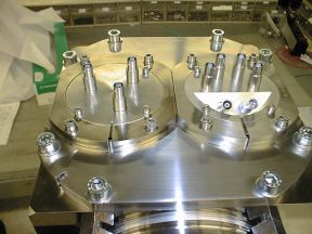
View of the top of the flight tube. The ion detector and accelerator assemblies were designed to be self-locating so they could be inserted into the vacuum chamber in only one way. The modular nature of the flight tube design aids in shipping and servicing the QSTAR.
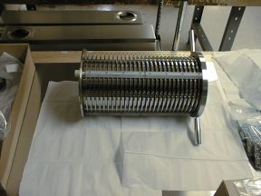
View of the reflector subassembly, a stack of resistors and metal rings that constitutes an important component of the flight tube. Using DFA software to analyze the design, the QSTAR team reduced the part count for the final assembly from 289 to 144. They also reduced the number of unique parts from 26 to 21. In the original breadboard design, each of the 32 resistors were mounted with four screws, an assembly process that took hours to accomplish. In the final design, press-in resistors require no separate fasteners.
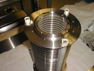
View of the top of the reflector subassembly. Only three screws and three nuts hold this assembly of 144 parts together. Assembly time is just 45 minutes.
| Discover | Learn | BDI Info | Follow Us |
| Software | Studies | About BDI |

|
| Solutions | Webinars | Contact |

|
| Training | News | Directions |

|
| Services | Papers | Agents | |
| Support | Forum | Partners |
DFMA and Concurrent Costing are registered trademarks of Boothroyd Dewhurst, Inc.
© Boothroyd Dewhurst, Inc. All rights reserved. Privacy Statement.