BOOTHROYD DEWHURST, Inc.


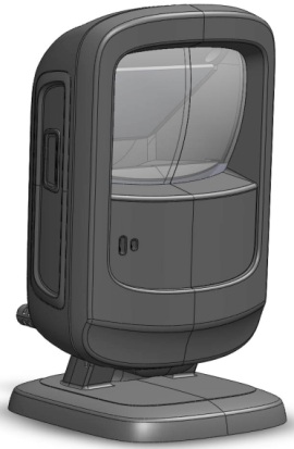
Boothroyd and Dewhurst’s DFA Software Drives Cost Savings for Motorola's DS9208 Scanner
Presented by: Chris Foley
At the International Forum on Design For Manufacture and Assembly
Introduction
In the beginning of this product development, as in all others at Motorola Solutions, cost savings were an important consideration and a team goal. If any potential cost savings could be identified, quantified and then implemented early on, this additional cost could then be avoided, thus reducing any direct and indirect costs of the product right from the beginning. Implementing these cost avoidances early on is when we would receive the most benefits.
Working closely with our Engineering Design Team at the concept stage of development and using the Boothroyd Dewhurst Design For Assembly Software, we were able to meet our cost savings objectives. This success allowed us to deliver a quality product, on time and on budget.
How did we do this?
Our process for developing a quality and cost efficient product requires that our Design Team and New Product Development Team work closely together, early on and during the entire development process. We do this in a number of different ways.
The first way we do this is to perform required, program-driven design reviews. These design reviews are spaced out along the development process of a new product. Usually the reviews are held during the decisive stages of the product development. These stages are Concept, Critical and Final. Concept reviews are held at the very beginning of a product when the very basic product features have been identified. Critical reviews are held when most, if not all of the parts have been identified. The Final reviews are held when all parts and their details are completed and are ready to go out for Tooling.
In addition to the standard reviews, we hold impromptu, drive-by reviews. These informal reviews are held whenever a situation arises or when the Design or Product Development Engineer considers it to be necessary. In this more personal, one-n-one environment, more issues can often be addressed and resolved, than in more formal settings.
In addition to the Design reviews, the New Product Development Team has as a deliverable requirement for all of these reviews, to perform a Boothroyd and Dewhurst, Design For Assembly review. This helps us supply near real-time feedback, to the Design Engineering Team. This is very important because if a part or features of a part are identified to be eliminated or changed, valuable design time and resource allocation can be saved. This could save days or even weeks off a large program’s design schedule.
Using Boothroyd Dewhurst’s DFA Software to Drive Cost Savings
During our formal and informal design reviews, we use the BDI DFA Software to help identify items to be eliminated, labor reductions, cost savings, drive potential overhead cost reductions, and steer the concept to an assembly-friendly design while helping drive higher Quality standards in our products.
The following are just a few samples: Note: Exact times and costs are proprietary and the following examples are adjusted to reflect the intent of this paper.
Springs (2)
Springs were needed to generate the energy for the ratcheting effect of the unit. The original design had the Springs installed on short posts which had to be in a precise location for assembly to function properly. This had potential for the Springs to shift during assembly and this failure would not be identified until after the unit was closed up. If this happened this would then cause a potential rework effort (Quality issue) for Manufacturing and possible future Service issues.
BDI Minimum Part Criteria: Movement
| Design Phase | Est. Cost | Est. Cost of Business Savings (COB)* | Quality Improvement | Percent Savings |
| Concept | $0.38 | N/A | N/A | N/A |
| Final | $0.09 | N/A | YES | 76% |
* Cost of Business = The cost of designing a new part, creating a new SKU, ordering, stocking, pulling from stock, warehouse real-estate, Quality, Service, WIP, etc…. Basically, any Overhead function where it is hard to capture a solid savings. These could be anywhere from a simple Screw at $5,000 over the life of a product, or a complex PCB or Casting at $20,000 in Overhead costs.
To achieve these savings, we focused on the Securing Method and Handling Difficulties questions in the BDI Software.
Ratchets (2)
Like Springs, Ratchets were needed to hold the product at a variety of specific angles that the customer can easily set. Originally, there was a Right and a Left Ratchet design. Also, each Ratchet had to be installed in a specific orientation in the same pocket as the Springs. Because of the size and almost symmetrical design, the operator had to view each Ratchet, orientate it appropriately and then fit it into the appropriate (left or right) pocket.
Minimum Part Criteria: Movement
| Design Phase | Est. Cost | Est. Cost of Business Savings (COB)* | Quality Improvement | Percent Savings |
| Concept | $0.51 | N/A | N/A | N/A |
| Final | $0.10 | YES | YES | 80% |
Reviewing the BDI DFA Software output, we focused first on the Minimum Part Criteria, Symmetry and then Insertion Difficulties.
Sound Chamber (1) and Gasket (1)
The sound chamber is a uniquely tuned part that amplifies the audio output of a speaker, beeper or any other sound producing device. To seal the unit to keep dust and liquids away from the electronics we typically use a rubber Gasket.
Minimum Part Criteria: Material and Other
| Design Phase | Est. Cost | Est. Cost of Business Savings (COB)* | Quality Improvement | Percent Savings |
| Concept | $0.60 +$0.40 | N/A | N/A | N/A |
| Final | $0.95 | YES | YES | 5% |
Again, focusing on the first rule of the BDI DFA Software, Minimum Part Criteria, is to ask if this part really needed or can it be combined with another part.
Exit Window (1)
One of the most important parts of the product is the Exit Window. The Window is made from Glass or optical plastics and acts as the eye of the product. As with anything optical, cleanliness is the utmost priority. Any time a Window is handled in the manufacturing process from the Supplier all the way through to the final assembly operator on the manufacturing line, there is an opportunity for the Window to become dirty. It is the operator’s responsibility to verify the Window is clean and if not, to clean it. Having to clean a Window adds no value, adds cost to the product and has potential to drive Quality defects.
Minimum Part Criteria: Material
| Design Phase | Est. Cost | Est. Cost of Business Savings (COB)* | Quality Improvement | Percent Savings |
| Concept | $0.30 | N/A | N/A | N/A |
| Final | $0.06 | N/A | YES | 80% |
Since the driving concern was keeping the Window clean from the Supplier to the end user, we focused on two aspects of the Design For Assembly Software, Handling Difficulties and Insertion Difficulties . If we could keep the Window clean, we would not have to re-clean it.
Window Gasket (1)
The Window Gasket seals the unit from dust and water intrusion. This part could also be combined with the Front Housing, thus eliminating a part. However, combining it with the Front Housing was not practical for cost and logistics issues. There was a requirement that an Antenna be incorporated into some models of this product. The Antenna is a double twisted wire loop. This wire loop Antenna must wrap around the front of the Housing near the Window.
Minimum Part Criteria: Other
| Design Phase | Est. Cost | Est. Cost of Business Savings (COB)* | Quality Improvement | Percent Savings |
| Concept | $0.10 | N/A | N/A | N/A |
| Final | $0.06 | YES | YES | 40% |
Creating features in the Window Gasket for the wire loop Antenna, we were able to give the operator features to easily and consistently install the Antenna. Thus, addressing the Insertion Difficulties or having to create an additional part.
Designing features into the Gasket allowed us to add value to a part who’s Minimum Part Criteria was Other. By eliminating the need to create an additional part to mount and hold the Antenna, we did not have to increase out part count. With these added features, the placement of the Antenna became precise and repeatability improved. This added Quality to the product.
Screw (1)
A counterweight was needed in the Base of this product. This was to be held in by three Screws. Two Screws of one length and a shorter one. This was because of certain design features that could not change. Screws were needed because the product had to survive specific drop requirements and a positive hold force was required to hold the weight in position.
Minimum Part Criteria: Fastener
| Design Phase | Est. Cost | Est. Cost of Business Savings (COB)* | Quality Improvement | Percent Savings |
| Concept | $0.15 | N/A | N/A | N/A |
| Final | $0.06 | YES | YES | 40% |
A lip was created in the Base that allowed us to remove the requirement for the single shorter Screw. Removing this requirement for this single use, shorter, Screw allowed us to eliminate a Fastener.
Adding a lip to the Base eliminate the use of a single Fastener. This saved Material and Labor costs. Eliminating the requirement for the shorter Fastener removed the possibility that a longer Screw could be driven into the shorter hole. If this happened and the Base was damaged, it would then have to be disassembled and replaced. Another potential Quality improvement.
Conclusion
The use of the Boothroyd Dewhurst DFA Software was instrumental in being able to quickly and easily identify product cost drivers. When reviewing each component of the product, we asked out ourselves, “What is driving the cost of assembling this part into the product?” We reviewed the BDI output and saw that most of our concerns could be addressed by revisiting just four of the key attributes of Boothroyd Dewhurst Design For Assembly Software, Minimum Part Criteria, Handling Difficulties, Insertion Difficulties and Symmetry. With this information, the team could, without delay, focus on the high end cost drivers that had been identified.
Working closely with Engineering very early in the development cycle of this program, we were able to achieve substantial cost avoidances. This allowed us to realize these savings up front, where they have the greatest impact. Not only were we able to identify direct savings in Labor and Material costs, additional intangible overhead savings were also realized.
The use of Boothroyd Dewhurst Design For Assembly Software was beneficial in pointing the way to eliminate parts, helping us drive reduced Labor and Material costs and to improve the Quality of our DS9208 Scanner.
 DFMA: SHOULD COSTING
 DFMA: PRODUCT SIMPLIFICATION