BOOTHROYD DEWHURST, Inc.


Look! Up in the Sky! 27% Fewer Parts!! 51% Cheaper!!!
Embry-Riddle Aeronautical University student uses DFMA to refine the design of a robotic monocopter
Since the time of DaVinci, inventors and engineers have wrestled with aviation design challenges. Here are a couple for today. Aeronautics challenge number one: Build a flying machine that imitates the aerodynamics of a maple seed—a nature-mimicry design problem that has stumped engineers for the past sixty years. Aeronautics challenge number two: Fly an unmanned vehicle inside a closed structure—one of the last remaining frontiers in the growing world of unmanned aerial systems (UAS) and vehicles (UAV). Now, both of these challenges have been successfully solved with one design—a biologically-inspired, robotic monocopter.
The aircraft that accomplished these aviation feats was designed and built by a team from Embry- Riddle Aeronautical University of Daytona Beach, FL—a world leader in aviation and aerospace education—and was entered in the 19th International Aerial Robotics Competition (IARC) sponsored by the Association for Unmanned Vehicle Systems International (AUVSI) (see Sidebar 1). The ingenious craft with the unusual flight-style placed third in the competition, won an award for “Most Innovative Air Vehicle,” and captured the imagination of everyone who saw it fly. With thoughts of commercialization for the toy and hobby market, the student-led team brought their UAV design into a fall-term course on Design for Manufacture and Assembly (DFMA).
Imagination meets manufacturing and assembly in the classroom
“This DFMA course is reality-based and bridges the gap between academics and industry,” said Sathya Gangadharan, professor of mechanical engineering at Embry-Riddle. “A lot of times when students and practicing engineers do a design, they don’t look at the practical aspects or cost implications of manufacturing the product.” For the course, students have to select a product that has between 15 and 30 components and then use DFMA to come up with modified designs. These new designs explore alternative materials and manufacturing processes which, in the end, allow the teams to preserve or improve features and functionality while reducing part count and cost. Gangadharan heard about DFMA software three to four years ago and first taught a course on the subject last year.
Graduate student Christopher Hockley brought the competition-tested monocopter to the class looking to make improvements. Prior to this, his team had considered several designs, choosing the maple-seed-inspired version: simple and elegant, with a single foamed wing, a thermo-plastic fuselage, a foam landing gear or foot, a carbon-fiber spar to give the wing rigidity, a plastic fan, and only two moving parts in all (see Figure 1). Because of the inspiration from the maple seed—or samara, meaning winged-seed—and the sensor requirements of the design, they named the aircraft the SamarEye. But samara-derivative aircraft, as well as monocopters in general, have not gained much attention or acceptance, so there was very little existing design information (fewer than 10 papers on powered monocopters). As a result, the team was really on its own when it came to design and materials (see Sidebar 2).
The team was also working in the dark when it came to cost, assembly, and manufacturing considerations as they prepped for the IARC event. “We only thought about how to make the individual parts,” said Hockley, “so when it came time to put it together, we didn’t have a clue.” As a result, manufacturing time took much too long (approximately 40 man-hours) and hot glue in large quantities was the fastener of choice. After the competition, some critical thinking was obviously needed to improve assembly and manufacturing and to see the aircraft not as a collection of separate parts but as an integrated, holistic system. The DFMA course provided the perfect vehicle for rethinking the design.
Asking the right questions early in the design process
DFMA is an integrated suite of software solutions from Boothroyd Dewhurst, Inc., Wakefield, RI that helps engineers ask critical questions about their product designs early in the development process. Such an evaluation can have major impacts downstream on the manufacturing, assembly, and cost of those products.
Design for Assembly (DFA) software guides engineers to simplify a design using queries—such as whether parts move with respect to one another or whether they can be made of the same materials—the answers to which lead to reduced part count and cost. Functional efficiency, fewer parts, and ease of assembly are the goals.
Design for Manufacture (DFM) software complements DFA, providing engineers with a structured way to examine process technology and material choices in order to anticipate manufacturing costs early in the product development life cycle. Manufacturing knowledge and reduced costs are the payoffs here. By asking the right questions up front, all of the cost-implications of designs can be taken into account, rather than popping up later after the design has been locked-in.
“With DFMA we’re trying to solve a number of engineering problems,” said Hockley. “By reducing part count, we’re hopefully going to have a flying machine that not only works better, but is more weight-efficient, more weight-economical, and structurally stronger. We’re also looking to make it more repeatable for manufacture. That’s a big thing.”
Students in the DFMA class follow a realistic design process, incorporating CAD, FEA, and tolerancing. “First, they model the part or product using CATIA to produce 3D views,” said Gangadharan (see Figure 2). “Next, they perform FEA and calculate data on stress, deformation, and frequency constraints. Then they must tolerance the parts.” Following this baseline design work, students then use the DFMA software modules to evaluate and refine their designs, using FEA in a feedback loop to prove out the functionality of their DFMA design changes.
Analyzing the monocopter baseline design using DFMA
The student team’s SamarEye monocopter design was 71cm long, 184 grams in weight, and had 18 parts, eight of which were provided by outside sources. Of the remaining 10 parts to be manufactured, six were extruded and four were thermoformed, and all were of similar size except for the wing. This kept manufacturing costs low to begin with, as common injection molding and thermoforming equipment could be purchased with only the dies varying. Despite the aircraft’s light weight and comparatively weaker materials, the baseline design was structurally strong and had an ample factor of safety under typical operating conditions.
Using a projected product life volume of 100,000 and a batch size of 12,500, Hockley ran a DFMA analysis of the original design and determined that the cost of tooling was $2.55, the piece part cost was $4.25, and the assembly cost was $7.08 for a total cost per product of $13.88. Despite the fact that the baseline design had relatively few parts and that the manufacturing methods were already relatively simple, the analysis demonstrated that there was still room for improvement. Of the 10 manufactured parts, three of them—the fuselage top, fuselage bottom, and the wing—were the most expensive and therefore of most interest. As for assembly, more than 50 percent of the total product cost resulted from this activity, representing the greatest room for improvement of any design-to-cost variable.
Refining the monocopter baseline design
Following the DFMA analysis in which the processes and components representing the greatest waste were identified, Hockley evaluated the design to see where improvements could be made. In the baseline design, the wing—the single largest piece—was made out of an expanded polystyrene thermoplastic (used as floor insulation) while the fuselage was made out of a PETG thermoplastic (used for clamshell packaging).
In the modified design, the team decided to combine the wing, fuselage, and main gear into one injection-molded polystyrene foam piece, with the main spar and fan housing molded in place (see Figure 3). “These changes not only removed a number of components,” said Hockley, “but reduced the number of operations required in assembly.” With the switch in materials from the stronger PETG to the weaker polystyrene, additional iterative FEA simulations were required to ensure that the aircraft could withstand all loading scenarios (see Sidebar 3).
DFMA leads to significant cost and time improvements
“In the redesign, I cut the parts down from 18 to 13, eliminating five manufactured parts,” said Hockley. This consolidation was the result of combining parts that shared materials or did not have motion relative to one another. Reducing parts and streamlining the assembly process can cut manufacturing costs in a number of ways, according to Hockley. “It can reduce the number of molds required for part production, decrease the type and quantity of machinery required, and simplify the storage of parts on the shop floor.” Another benefit of parts consolidation is a reduction in part interfaces, which improves quality by helping eliminate stress at joints and fasteners. “Consolidation of parts,” Gangadharan added, “improves FEA performance—an outcome that often gets overlooked by designers and analysts.”
With commercialization of the monocopter in mind, Hockley is excited by the final DFMA results for his class project: piece part cost reduction of 25 percent; overall product cost reduction of 51 percent; assembly labor time and cost reduction of 74 percent; and a grand total savings of 625 days and $717,000 for a production run of 12,500 (see Figure 4). Such savings are huge, when you need to keep an eye on what rings up at the register, and can be the difference between commercial success or failure.
Gangadharan is a champion for the lessons that DFMA can teach the next generation of engineers. “In the aerospace industry, and more specifically in the UAV market, it is becoming increasingly important to maximize functionality while minimizing cost,” he said. “DFMA is the perfect tool for accomplishing this.”
“The engineering students’ success in industry depends on how close to reality they are able to think,” he added. With the AUVSI competition having demonstrated the SamarEye monocopter’s navigational skills, DFMA should help the craft’s designers begin navigating commercial markets as well.
Sidebar 1. The International Aerial Robotics Competition
The 19th annual International Aerial Robotics Competition (IARC) was held in the summer of 2009 at the University of Puerto Rico in Mayagüez. Sponsored by the Association for Unmanned Vehicle Systems International (AUVSI), the mission for this year’s competition, Inside the Box, pushed the boundaries of autonomous aerial system capabilities by requiring the exploration of a complex, closed environment. The competition was open to university students worldwide.
This year’s mission rules required an aerial robot to be launched from a mother ship outside the target building, enter through a one meter square window, search an 18 by 33 meter building until it finds a blue LED gauge, and create a map of the building while searching. The system had to then transmit the map, the location of the target, and the target imagery back to the mother ship using the Joint Architecture for Unmanned Systems (JAUS) protocol.
Autonomous flight in a Closed Quarter Environment (CQE) is one of the last remaining frontiers in which unmanned aerial systems (UAS) have yet to gain acceptance. Conventional UAS and aircraft paradigms are inadequate for this difficult mission with design challenges including: the power density and efficiency of propulsive systems; on-board computational capability; and methods of rapidly and programmatically traversing complex environments. The capabilities required for this competition have obvious defense applications but also can be used in search and rescue, fire monitoring, law enforcement, and a variety of other applications.
Sidebar 2. Maple seed and monocopter aerodynamics
Inspired by helicoptering tree seeds, aerospace engineers have finally cracked a 60-year old engineering aviation challenge: to create an aircraft that copies the seemingly simple, yet effective, aerodynamic flight of a maple seed. Winged tree seeds, or samara—such as the maple, elm, and ash—use a spinning rotary motion (auto-rotation), which generates a leading-edge vortex to reduce air pressure over the seed-wing and create lift. This evolutionary aerodynamic solution serves as a dispersal mechanism to ensure propagation of new trees as far from the parent tree as possible. Scientists report that the slowly falling seeds can be carried more than a mile by favorable winds.
Graduate student engineers at Embry-Riddle Aeronautical University in Daytona Beach, FL used the wing shape and rotary motion of the maple seed as the basis for an unmanned monocopter design. Previous monocopters had been plagued by instability inherent in single component, fixed-winged designs. The Embry-Riddle free rotor craft (the entire vehicle rotates) solved this problem with a design that included six degrees of freedom using only two actuators: an electric ducted fan and a responsive control flap on the wing. The Hiller-type flap trails the wing by 90 degrees and works similarly to the cyclic control on a conventional helicopter or the elevator on a conventional airplane. Sensor requirements for navigating were reduced since any fixed sensor became a scanning sensor due to vehicle rotation.
Scientists have recently unlocked the secrets of maple seed flight using slow motion films of seed models rotating in a laser-illuminated glass bead and mineral oil mixture, as well as actual seeds whirling in wind tunnel smoke simulations. Borrowing from nature’s grand design manual, several other teams have also recently designed maple seed related UAVs.
Sidebar 3. Using DFMA and FEA to validate design changes
Monocopters operate in a very demanding flight regime, experiencing a complex mix of aerodynamic and gyroscopic forces. When looking to improve the design of the SamarEye monocopter for commercialization, the Embry-Riddle student-team used a combination of DFMA analysis (to explore alternative material choices and design variables) and FEA (to ensure that proposed changes could withstand all loading scenarios). Aerodynamic loads can be broken down into lift and drag.
However, the most severe loading for the monocopter is gyroscopic, resulting from a rotational frequency of 460 rpm that produces a radial acceleration on the motor mount 39 times the force of gravity.
For the original design, gyroscopic loading was examined using FEA of the fuselage housing; this analysis demonstrated that the materials were significantly below the failure point when subject to flight conditions. To compute the aerodynamic loads on the single wing, FEA was again used in conjunction with blade element momentum theory (BEMT). With uniform pressure applied to the wing, a finite element model validated that the wing and its embedded carbon fiber spar were not overloaded and performed in keeping with observations in the IARC competition.
Following the competition, DFMA analysis was used to identify waste, consolidate parts, and reduce the assembly cost of the monocopter. As a result of the analysis, the team determined that a significant cost-savings could be realized by merging the wing, fuselage, main gear, and embedded spar into one injection-molded piece using a different material than in the original design. To ensure that the new materials and design could withstand flight loading, FEA was once again used in an iterative fashion as multiple changes were made to the design to stiffen the wing against torsion and reduce stresses where the fan housing connected to the fairing.
According to mechanical engineering professor Sathya Gangadharan, “DFMA lowered part count and improved FEA performance of the design by eliminating the stress at joints and fasteners. It also helped to reduce the overall weight of the monocopter—an important outcome when dealing with UAVs—by validating lighter materials that are easily moldable and lower in cost.”
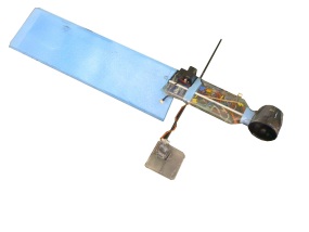
The SamarEye competition version monocopter has a single foamed wing, a thermo-plastic fuselage, a foam landing gear or foot, a carbon-fiber spar to give the wing rigidity, and a plastic fan.
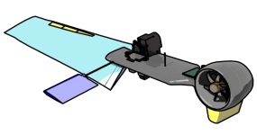
Shown is a CATIA model “cartoon view” of the competition SamarEye monocopter before DFMA redesign.
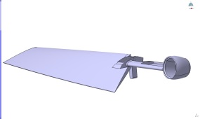
CATIA model of the DFMA redesigned SamarEye monocopter illustrates the simplification of the design, achieved by combining the wing, fuselage, and main gear into a single injection-molded foam piece.
| Baseline | Redesign | |
| Product life volume | 100,000 | 100,000 |
| DFA Index | 1.2 | 6.5 |
| Total assembly labor time | 722.63 | 181.95 |
| Total manufacturing cost including tooling | $6.80 | $4.93 |
| Total assembly labor cost | $7.08 | $1.78 |
| Total manufacturing peice part cost | $4.25 | $3.24 |
| Total cost per product without tooling | $11.33 | $5.02 |
| Manufacturing tooling cost per product | $2.55 | $1.69 |
| Total cost per product | $13.88 | $6.71 |
Comparison between the DFMA results for the original baseline design and the modified redesign of the SamarEye monocopter. Note the substantial savings in total assembly labor time and cost, as well as total cost per product.
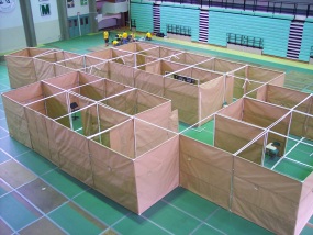
Inside the Box, the International Aerial Robotics Competition’s (IARC) mission, involved flying an aerial robot through an enclosed maze-like structure. The robot navigated and mapped the environment while locating a target object and sending all of the information back to a mother vehicle.
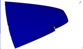
In the original design of the monocopter, loads are concentrated at a single joint where the spar embedded in the wing would attach to a separate fuselage piece; in this design the wing itself bears almost no load.
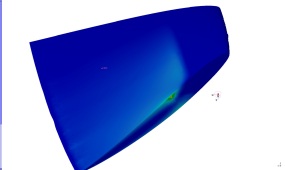
In the modified design, following DFMA analysis, the wing and fuselage have been simplified into a single injection-molded part. The FEA clearly illustrates how the loading is now more evenly distributed through the wing, instead of being concentrated at a single point. It also illustrates how parts consolidation and reduction in joints and fasteners leads to improved structural integrity.
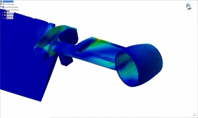
The modified design is shown with the fuselage attached to further illustrate the distribution of loads in a single-piece design.
 DFMA: SHOULD COSTING
 DFMA: PRODUCT SIMPLIFICATION